Profile Panels
/in Data Fields configuration, contact id, data fields, device, Hardware, Profiles, template /by Steve BartonReader
Readers are used to perform user interactions on a door. The reader will inherit the properties of a Door for allowing users to present cards or enter pins. There is no need to have any schedules attached to a Reader.
Name – Needs to be unique for each controller. Requires alphanumeric characters with no spaces with a maximum length of 255. | |
Description – Requires alphanumeric characters with a maximum length of 255. Does not need to be unique. | |
Logical ID – Numerical value. The unique identifier assigned to a device connected to the S1000 Control Panel. | |
Device – Select from the pop-up menu. | |
| – Controller – Third-party Wiegand readers. |
| – Keypad – SPG Keypad readers. |
Physical ID on Device – Numerical value. Unique identifier configured into the device. | |
Area – Select from the pop-up menu. | |
Report Events – Toggle ON or OFF to record reader events. | |
High Priority – Toggle ON or OFF to assign high priority. |
Doors
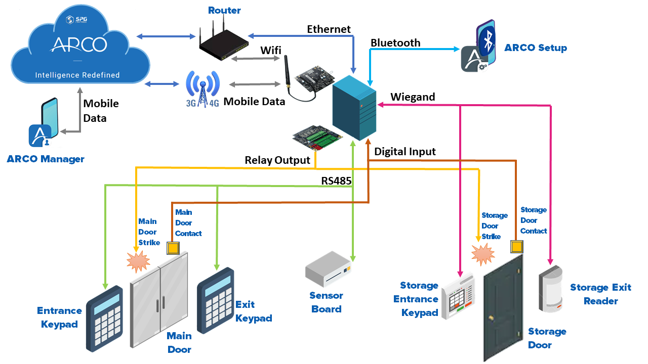
ARCO Platform enables the support of up to eight (8) Doors in a single S1000 Smart Controller. There are a series of properties that determine the behaviour of the door. Each Door can have up to two (2) readers attached (one on each side of the door), one egress input, one door strike output, one door contact input and one strike contact input.
Name – Needs to be unique for each controller. Requires alphanumeric characters with no spaces with a maximum length of 255. | |
Description – Requires alphanumeric characters with a maximum length of 255. Does not need to be unique. | |
Logical ID – Numerical value. The unique identifier assigned to a device connected to the S1000 Control Panel. | |
Reader In – Select from the drop-down menu. Card or Keypad reader assigned to enter the door. | |
Reader Out – Select from the drop-down menu. Card or Keypad reader assigned to exit the door. | |
Door Contact Input – Select from the drop-down menu. Defines the input on the controller to be used for Door Contact monitoring | |
Egress Input – Select from the drop-down menu. Defines the input on the controller to be used for the Egress to grant access to a door by using a pushbutton or similar. | |
Strike Output – Select from the drop-down menu. Defines the output on the controller to be used to activate the electronic strike on a door to allow the door to be opened. | |
Locked Schedule – Select from the drop-down menu. The schedule used to specify that this door remains locked. | |
Unlocked Schedule – Select from the drop-down menu. The schedule used to specify that this door remains unlocked. | |
Card and PIN Schedule – Select from the drop-down menu. Specify that this door requires card and pin to be used to access. | |
Card or PIN Schedule – Select from the drop-down menu. Specify that this door requires a card or pin to be used to access. If no schedule is defined, then Card Only will be the default | |
Egress Schedule– Select from the drop-down menu. Enable the egress button to be used. If no schedule is defined, then Egress will always work. | |
Strike Time (sec) – Numerical value. Time until the door opens. | |
Shunt Time (sec) – Numerical value. Time to allow the person to enter/exit. | |
Embarrassment Time (sec) – Numerical value. Time until to issue an embarrassment warning. | |
Lock – Select from the drop-down menu. Normal or Magnetic | |
Report Events – Toggle ON or OFF. | |
Do Not Send Forced – Toggle ON or OFF. | |
Do Not Send Ajar– Toggle ON or OFF. |
Door Schedules
If there are no door schedules defined, then the door will be in a mode that allows cards to be used to access (normal mode operation). If there is a door schedule for locked defined and the time schedule is valid, then the door remains in a locked state. If there is a door schedule defined and the time period is invalid, then the door is in the normal state or the state defined by the unlocked schedule. The locked schedule overrides the unlocked schedule. If there is an unlocked schedule defined, then the time period for unlocking the door is checked, and if valid, the door will be set to the unlocked state. If neither the locked nor unlocked schedules are defined, then the door remains in the normal state and will allow access using the normal access control procedure.
Please refer to the Schedules section below for further details.
Door Access
For access control operation, there is also a time schedule defined to determine the behaviour of the readers attached to the door. If there is a time schedule defined for Card plus PIN, then the reader will prompt for PIN entry after a card is presented. If there is no schedule defined or the time period is not valid for card plus PIN, then the reader will check for the schedule Card or PIN, and if this is defined, then the reader will allow for entry of a PIN or the swipe of a card. If there is no Card of PIN schedule defined or the time period is not valid, then the reader will default to card only mode. There is a setting on the system that defines that the entry of PIN requires an ID to be also entered.
Commands can be sent to a door to Lock and Unlock. These commands will override the current door settings set by the schedules. If a command to Lock, a door is sent then the door will remain locked for either the duration passed in the command or if the duration is 0 then it will remain locked indefinitely. There should be a different event sent for the locked status to indicate that the door is locked by a command. To exit this command lock state, you need to send a restore to normal command or the timer expired on the lock command. The same logic applies to an Unlock command. An access command will momentarily open the door and do the same operation as if a valid card has been entered. When the restore to normal command or timer expired on the command action, then the door returns to the normal state of the state that is set by the schedule for locked or unlocked.
Analog Inputs
ARCO enables you to customise your system using configurable alarm, access control and building monitoring analog data input.
Name – Needs to be unique for each controller. Requires alphanumeric characters with no spaces with a maximum length of 255. | |
Description – Requires alphanumeric characters with a maximum length of 255. Does not need to be unique. | |
Logical ID – Numerical value. The unique identifier assigned to a device connected to the S1000 Control Panel. | |
Device – Select from the drop-down menu. | |
Physical ID on Device – Numerical value. Unique identifier configured into the device. | |
Report Events – Toggle ON or OFF to report an event. | |
High Priority – Toggle ON or OFF to assign high priority. | |
Report to Alarm Monitoring Centre – Select the monitoring centre where the data will be sent. | |
Sensor Type – Select from the drop-down menu. | |
Reporting Frequency – Numerical value. Time in minutes on how often readings are reported under steady-state conditions when not exceeding the Tolerance value. | |
Tolerance – Numerical value. The amount of difference between the measured input and the previously measured input before triggering and alarm. | |
Compensation – Numerical value. Offset subtracted to input value for error correction. | |
Lower Value – Numerical value. Inputs below this value will trigger an alarm. | |
High Value – Numerical value. Inputs above this value will trigger an alarm. |
Pulse Counter
ARCO enables you to customise your system using configurable alarm, access control and building monitoring data input.
Name – Needs to be unique for each controller. Requires alphanumeric characters with no spaces with a maximum length of 255. | |
Description – Requires alphanumeric characters with a maximum length of 255. Does not need to be unique. | |
Input Logical ID – Numerical value. The unique identifier assigned to a device connected to the S1000 Control Panel. | |
Device – Select from the drop-down menu. | |
Physical ID on Device – Numerical value. Unique identifier configured into the device. | |
Report Events – Toggle ON or OFF to report an event. | |
High Priority – Toggle ON or OFF to assign high priority. | |
Report to Alarm Monitoring Centre – Select the monitoring centre where the data will be sent. | |
Polarity – Select from the drop-down menu. | |
Minimum Pulse – Numerical value. Time in minutes on how often readings are reported under steady-state conditions when not exceeding the Tolerance value. | |
Pulse Count – Numerical value. The amount of difference between the measured input and the previously measured input before triggering and alarm. | |
Reporting Frequency – Numerical value. Time in seconds on how often readings are reported. |
Inputs
ARCO enables you to customise your system using configurable alarm, access control and building monitoring data input.
Input Basic Settings
Name – Needs to be unique for each controller. Requires alphanumeric characters with no spaces with a maximum length of 255. | |
Description – Requires alphanumeric characters with a maximum length of 255. Does not need to be unique. | |
Logical ID – Numerical value. The unique identifier assigned to a device connected to the S1000 Control Panel. | |
Device – Select from the drop-down menu. | |
Physical ID on Device – Numerical value. Unique identifier configured into the device. | |
Category – Select from the drop-down menu. Define the type of data received from the input. | |
Area – Select from the drop-down menu. | |
Hit Count – Numerical value. | |
Latched – Toggle ON or OFF to latch input. | |
Latched (Tamper) – Toggle ON or OFF to latch tamper input. | |
Latched (Fault) – Toggle ON or OFF to latch fault input. | |
Is Egress – Toggle ON or OFF to mark as Egress. | |
Is Primary Entry – Toggle ON or OFF to mark as primary entry. | |
Is on Exit Path – Toggle ON or OFF to mark as exit path. | |
Is Secondary Entry – Toggle ON or OFF to mark as secondary entry. | |
Report Events – Toggle ON or OFF to report events. | |
High Priority – Toggle ON or OFF to assign high priority. |
Input Advanced Settings
Report Trouble as Sealed – Toggle ON or OFF | |
Monitor while in-active – Toggle ON or OFF | |
Report to Alarm Monitoring Centre – Select the monitoring centre where the data will be sent. | |
Alarm Resistance – Numerical value. | |
Alarm Normally Open – Toggle ON or OFF | |
Tamper Resistance – Numerical value. | |
Tamper Normally Open – Toggle ON or OFF | |
Range Reduction Resistance – Numerical value. | |
Range Reduction Normally Open – Toggle ON or OFF | |
Masking Resistance – Numerical value. | |
Masking Normally Open – Toggle ON or OFF | |
Fault Resistance – Numerical value. | |
Fault Normally Open – Toggle ON or OFF | |
Tolerance – Numerical value. |
Outputs
ARCO enables you to customise your system using configurable access control and building control data output.
Name – Needs to be unique for each controller. Requires alphanumeric characters with no spaces with a maximum length of 255. | |
Description – Requires alphanumeric characters with a maximum length of 255. Does not need to be unique. | |
Logical ID – Numerical value. The unique identifier assigned to a device connected to the S1000 Control Panel. | |
Device – Select from the drop-down menu. | |
Physical ID on Device – Numerical value. Unique identifier configured into the device. | |
Output Type – Select from the drop-down menu. | |
Normal – Generic output. | |
PIR – Passive Infrared Sensor. | |
Siren – Device that makes a prolonged loud sound as a signal or warning. | |
Strobe – Device used to produce regular flashes of light. | |
Camera – Video Recording device. | |
Report Events – Toggle ON or OFF to record reader events. | |
High Priority – Toggle ON or OFF to assign high priority. |
Timer
ARCO enables you to customise your system using configurable access control and building control data output.
Name – Needs to be unique for each controller. Requires alphanumeric characters with no spaces with a maximum length of 255. | |
Description – Requires alphanumeric characters with a maximum length of 255. Does not need to be unique. | |
Logical ID – Numerical value. The unique identifier assigned to a device connected to the S1000 Control Panel. |
Areas
ARCO Platform enables the support of up to eight (8) Areas in a single S1000 Smart Controller. There are a series of properties that determine the behaviour of the area.
Name – Needs to be unique for each controller. Requires alphanumeric characters with no spaces with a maximum length of 255. | |
Description – Requires alphanumeric characters with a maximum length of 255. Does not need to be unique. | |
Logical ID – Numerical value. The unique identifier assigned to a device connected to the S1000 Control Panel. | |
Disarm Schedule– Select from pop-up. | |
Auto Arm – Toggle ON or OFF | |
Dual User Mode – Select from pop-up. | |
Disable Area Count– Toggle ON or OFF | |
Entry Delay Fast (s) – Numerical value. | |
Entry Delay Slow (s) – Numerical value. | |
Exit Delay Fast (s) – Numerical value. | |
Exit Delay Slow (s) – Numerical value. | |
Report Events – Toggle ON or OFF to record reader events. | |
High Priority – Toggle ON or OFF to assign high priority. | |
Report to – Select the monitoring centre where the data will be sent. |
Area Configuration
The arm schedule is used to determine when the area is allowed to be disarmed and when the area is not allowed to be disarmed. If the time window is enabled, then this area is allowed to be disarmed. If this time window is disabled, then this area is not allowed to be disarmed. If an area is disarmed and the time window expires such that it is no longer allowed to be disarmed, then a late to close event is generated. There is a macro condition that is triggered when an area has a late to close. If a user is trying to disarm an area and the time window prevents them from disarming this area, then there should be a user group property to allow them to access this area outside hours. In this situation, the user will be granted access for a configured time window only. If the area schedule is set to 0, then this area is permanently armed by default. A user is allowed to extend the end window of the disarm period by using the keypad to select “extend disarm” which will extend the disarm period for an additional configurable time.
Microphone
Name – Needs to be unique for each controller. Requires alphanumeric characters with a maximum length of 255. |
Description – Requires alphanumeric characters with a maximum length of 255. Does not need to be unique. |
Device – Select from the drop-down menu. |
Physical ID on Device – Numerical value. The unique identifier assigned to a device connected to the S1000 Control Panel. |
Area – – Select from pop-up. |
Default Volume – Numerical value. |
Report Events – Toggle ON or OFF to record reader events. |
High Priority – Toggle ON or OFF to assign high priority. |
Report to – Select the monitoring centre where the data will be sent. |
Speaker
Name – Needs to be unique for each controller. Requires alphanumeric characters with a maximum length of 255. |
Description – Requires alphanumeric characters with a maximum length of 255. Does not need to be unique. |
Device – Select from the drop-down menu. |
Physical ID on Device – Numerical value. The unique identifier assigned to a device connected to the S1000 Control Panel. |
Area – – Select from pop-up. |
Default Volume – Numerical value. |
Report Events – Toggle ON or OFF to record reader events. |
High Priority – Toggle ON or OFF to assign high priority. |
Report to – Select the monitoring centre where the data will be sent. |
Interlock
Name – Needs to be unique for each controller. Requires alphanumeric characters with no spaces with a maximum length of 255. |
Description – Requires alphanumeric characters with a maximum length of 255. Does not need to be unique. |
Logical ID – Numerical value. The unique identifier assigned to a device connected to the S1000 Control Panel. |
Doors – Select from pop-up. |
Elevator
ARCO enables you to add an Elevator profile that of an S1000 Remote IO installed with one (1) IO Expansion Card and two (2) 6Output Expansion Cards. Each module controls and monitor one (1) elevator car for up to sixteen (16) floors. Additional floors are easily scalable by adding more modules.
Name – Needs to be unique for each controller. Requires alphanumeric characters with no spaces with a maximum length of 255. | |
Description – Requires alphanumeric characters with a maximum length of 255. Does not need to be unique. | |
Logical ID – Numerical value. The unique identifier assigned to a device connected to the S1000 Control Panel. | |
Reader – Select from pop-up. Reader to manage access to the elevator. | |
Secondary Reader – Select from pop-up. Reader to manage access to the elevator. | |
Reader Schedule – Select from pop-up. | |
Card and PIN Schedule – Select from pop-up. | |
Card or PIN Schedule – Select from pop-up. | |
Output On Duration – Numerical value in seconds. | |
Report Events – Toggle ON or OFF to record reader events. | |
High Priority – Toggle ON or OFF to assign high priority. | |
Report to – Select the monitoring centre where the data will be sent. | |
Floors – Click the Add floor button to select a Floor profile for the elevator. Click Clear all floors to remove. |
Floor
RCO enables you to create independent floor profiles to create specific access, properties and management.
Name – Needs to be unique for each controller. Requires alphanumeric characters with a maximum length of 255. | |
Description – Requires alphanumeric characters with a maximum length of 255. Does not need to be unique. | |
Logical ID – Numerical value. The unique identifier assigned to a device connected to the S1000 Control Panel. | |
Unlocked Schedule – Select from pop-up. |
Camera
ARCO enables you to add Cameras that can output their display on your Dashboard.
Name – Needs to be unique for each controller. Requires alphanumeric characters with a maximum length of 255. | |
Description – Requires alphanumeric characters with a maximum length of 255. Does not need to be unique. | |
Device – Select from the drop-down menu. | |
Physical ID on Device – Numerical value. The unique identifier assigned to a device connected to the S1000 Control Panel. |
Cameras are installed and configured based on its manufacturer’s instructions. |
Services
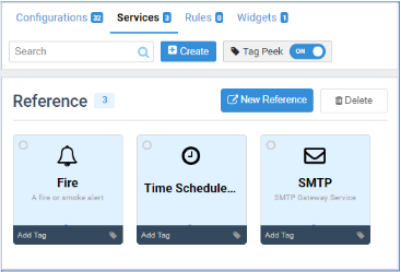
References
Alarm Type
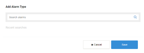
Please refer to the Alarm section below for further details. |
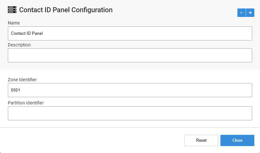
Contact ID
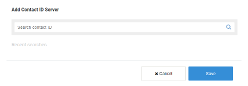
Please refer to the Contact ID section below for further details. |
Schedule
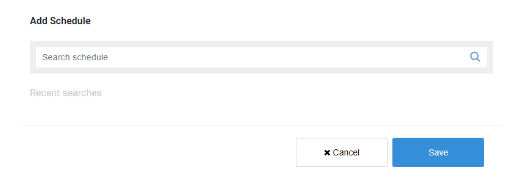
Please refer to the Schedules section below for further details. |
Rules
Lorem ipsum dolor sit amet, consectetur adipiscing elit. Ut elit tellus, luctus nec ullamcorper mattis, pulvinar dapibus leo.
-
Rule Name – Needs to be unique to each profile. Requires alphanumeric characters with no spaces and a maximum length of 255.
-
Run on device – Toggle ON or OFF. Save the rule on the S1000 Smart Controller to run even when offline.
-
Condition match – Select using the tick box.
-> All condition match – All conditions must match to run the rule.
-> Any conditions match – Only one condition must match to run the rule. -
Conditions – Select from the drop-down menu.
-> Select point type – Select from the drop-down menu.
-> Select event – Select from the drop-down menu.
-> Select status – Select from the drop-down menu. -
Add new condition – Click to create a new condition field.
The required fields may look different depending on your System Configuration.
-
Actions – Select from the drop-down menu. Action to be performed if the condition results are true.
-> Target – Select from the drop-down menu.
-> Action – Select from the drop-down menu. -
Duration – Check to set time of action duration.
-
Add action – Click to create a new action field.
-
Conditions – Select from the drop-down menu.
->Select point type – Select from the drop-down menu.
->Select event – Select from the drop-down menu.
->Select status – Select from the drop-down menu.
The required fields may look different depending on your System Configuration.