Location Management
-
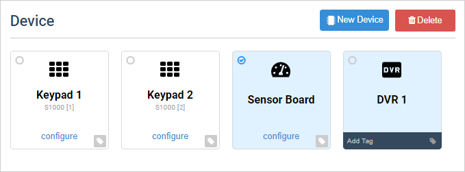
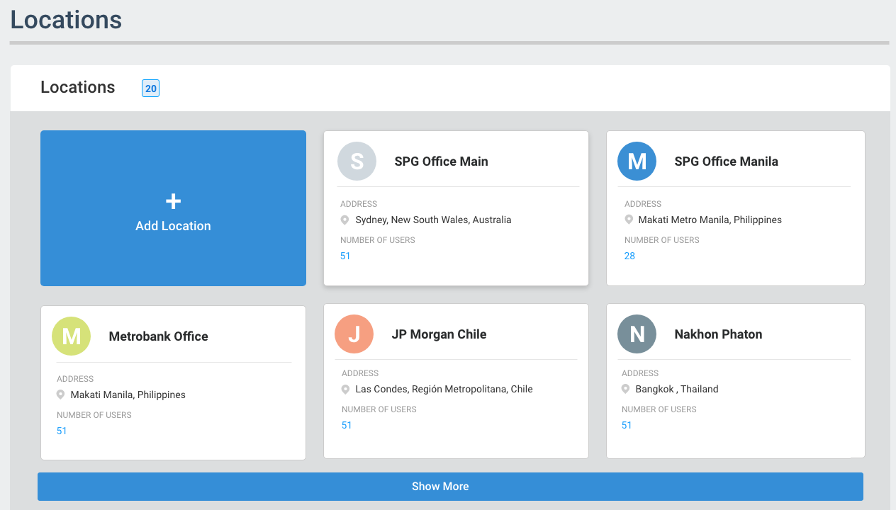
Location Count – Number of Locations currently in the system.
-
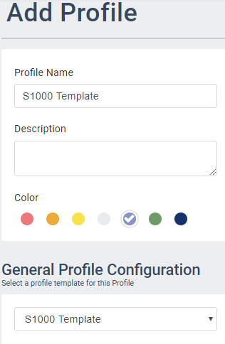
Add Location button – Enables you to add a new Location in ARCO. The next section will discuss the full details about adding sites.
-
Card Panel – Displays the details of the Location. Click to view Location information.
-
Show More – Click to display more Locations.